SDS Model 48 Spray Dryer


Small Scale Production of Spray Dried Powders

Pilot and R&D Spray Dryers

Site Map  
Small Scale Dryers
Model 48 Spray Dryer
Model 60 Spray Dryer
Model 72 Spray Dryer


SDS SMALL SCALE SPRAY DRYER PHOTO GALLERY

Below are selected pictures of SDS Small Scale spray dryer system components in various stages of fabrication, installation, and start up.  Click on a picture for an enlarged view.

THE SPRAY DRYER CHAMBER AND IT'S VARIATIONS AND FEATURES

A Model 48 spray dryer with chamber bottom product separation accessed by portable stairs.

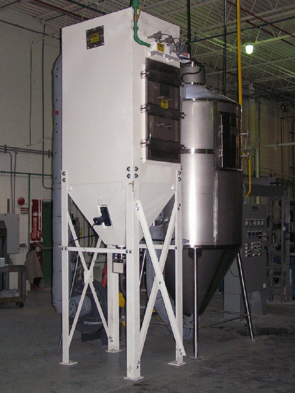
A Model 48 spray dryer with chamber bottom product separation, cyclone, and bag house.

A Model 48 spray dryer with cyclone and bag house collection.

A Model 48 spray dryer with cyclone and bag house collection.

A Model 48 spray dryer with bag house only product collection.

A Model 48 spray dryer with co-current nozzle, accessesed by a permanent platform.

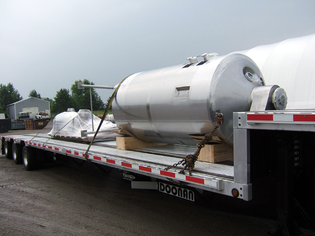
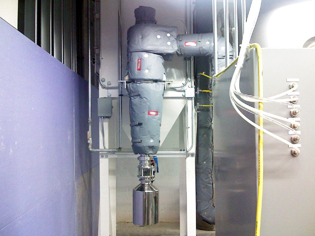
Model 48 with no chamber bottom product separation. Removable insulation covers the dryer outlet duct.

Observation ports are used to inspect the nozzle operation, and to ensure the dryer walls are remaining dry. This is a mixed flow nozzle dryer.

Model 48 with spray nozzle and observation ports at the top in the co-current configuration.

An air hammer, which provides timed "knocks" on the chamber to aide in powder flow.

A rapping pad, which is used with a rubber mallet to provide a manual aide in powder flow.

A typical pressure pump feed system layout with inlet and outlet pipe manifolds.

The spray lance installed and feed hose connected.

An installed mixed flow spray nozzle lance.

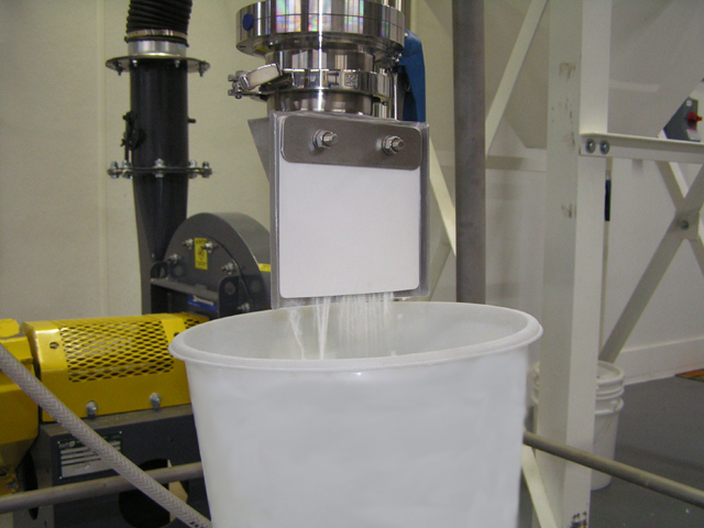
A co-current pressure nozzle spraying product.

The spray dryer access door.

The access door handles.

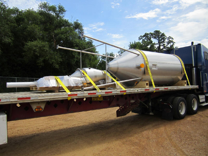
A Model 48 dryer being set upright in place.

PRODUCT COLLECTION OPTIONS

Dryer chamber product outlet with a vacuum flap airlock to discharge into an open container.

Dryer chamber fitted with two actuated butterfly valves for air lock to discharge into sieve screen.

A cyclone with a vacuum flap valve air lock for discharging into an open container, such as a drum.

A cyclone with removable insulation with a tri-clamp isolation valve, sight glass, and SS container.

A cyclone with removable insulation with a tri-clamp isolation valve, sight glass, and hose adaptor.

Baghouse outlet with tri-clamp valve and hose adapator for collection in a sealed container, such as this 5 gallon bucket.

THE AIR HEATER SYSTEM

Pre-piped and wired natural gas fuel train mounted on a wall near the spray dryer.

Pre-piped and wired natural gas fuel train located in a convenient place near the spray dryer.

The fuel train operation being shop tested along with the control panel.

The air heater housing with the burner mounted inside, with an inlet air filter attached, fuel piped up, and spark plug and flame rod wired.

A section of the control panel with the burner start/stop/reset buttons and indicator lights.

The alarm section of the control panel, including several burner safety control alarms.

AT THE FABRICATION SHOP

A Model 60 spray dryer, cyclone, and air heater fabricated, loaded, and shipping to our client.

The air heater housing being fit up to the dryer chamber.

Checking the burner installation in the heater housing.

The heater housing and cyclone being prepared for shipment.

A mixed-flow pressure nozzle spray lance checked for correct fabrication.

Another Model 48 dryer and other fabricated accessories loaded and ready to ship.


Home | Company | Photo Gallery | Video Gallery | Contact Us

All materials property of Spray Drying Systems, Inc. © 2014